Rotary Encoder Wiring Diagram Joystick
Why the switch of pinout when using breakout for the rotary encoder Wiring the cable: arduino rotary encoder wiring Jc24 joystick controller
How to use Rotary Encoder with Arduino
Stepper motor angle control using rotary encoder Encoder rotary without circuit code arduino work schematic pins example connecting using 5v topic debounce exchange works does hook schemata Rotary encoder diagram science creative switch works encoders helps next show click
Dc motor controller using rotary encoder
How to use rotary encoder with arduinoArduino encoder rotary circuit diagram use pcb simple breadboard assemble demonstration same Encoder rotary stepper wiring connections 5v wires in2 in1Rotary encoder wiring diagram.
🔴 rotary encoder connection/wiring with vfd/ac drive/dc drive, encoderEncoder rotary arduino incremental cable The creative science centreWiring the cable: arduino rotary encoder wiring.

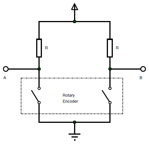
Rotary encoder schematic and example code
Rotary encoder with arduino ~ engineering projectsRotary encoder switch encoders optical shaft use gif mechanical indicators switches Rotation rotates switchesRotary joystick controller encoders connected similarly above.
Encoder rotary wiring driver direction d529 joystickEncoder wiring rotary connection drive vfd dc ac checking Encoder stepper arduino nano module engineersgarageEncoder pinout breakout raspberry push knob pi dummies soldering.

Rotary encoder
Switches & indicators .
.


JC24 Joystick Controller

🔴 Rotary Encoder Connection/Wiring with VFD/AC Drive/DC DRIVE, Encoder

Stepper motor angle control using rotary encoder

How to use Rotary Encoder with Arduino

Rotary Encoder schematic and example code

DC motor controller using rotary encoder

Wiring The Cable: Arduino Rotary Encoder Wiring

Switches & Indicators
Rotary Encoder With Arduino ~ ENGINEERING PROJECTS